|
Cisco Memory
Select your cisco system...
|
Cisco Memory Upgrade Information from CiscoMemoryUpgrade.comUpgrading Memory in Cisco 4000 Series RoutersProduct Numbers:
Note In this document, references to the Cisco 4000 series mean all routers in the series. References to the Cisco 4000 router or to another individual router mean only that router. Note When a procedure refers to the left side or right side of the chassis, component tray, or motherboard, unless otherwise specified, it means as viewed from the front. Use this document in conjunction with your router installation guide and the Cisco 4000 Series Public Network Certification document. To see translated versions of the Warnings in this document, refer to the Cisco 4000 Series Installation Guide. If you have questions or need help, refer to the sections �Cisco Documentation� and �Cisco Connection Online� later in this document. This document contains the following sections: Warning : Only trained and qualified personnel should be allowed to install or replace this equipment. Warning : Before working on a system that has an ON/OFF switch, turn OFF the power and unplug the power cord. The following Warning applies to routers with a DC power supply: Warning : Before performing any of the following procedures, ensure that power is removed from the DC circuit. To ensure that all power is OFF, locate the circuit breaker on the panel board that services the DC circuit, switch the circuit breaker to the OFF position, and tape the switch handle of the circuit breaker in the OFF position. Caution: To avoid damaging electrostatic discharge (ESD)-sensitive components, ensure that you have discharged all static electricity from your body before opening the chassis. Before performing procedures described in this document, review the next section, �Safety Recommendations.�
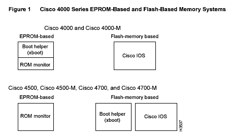
Warning : The Ethernet 10BaseT, Token Ring, serial, console, and auxiliary ports contain safety extra-low voltage (SELV) circuits. BRI circuits are treated like telephone-network voltage (TNV) circuits. Avoid connecting SELV circuits to TNV circuits. Safety with Electricity � EPROM stores the ROM monitor and the boot helper in the Cisco 4000 and the Cisco 4000-M. In the Cisco 4500, Cisco 4500-M, Cisco 4700, and Cisco 4700-M routers, EPROM stores only the ROM monitor; the boot helper is stored in Flash memory.
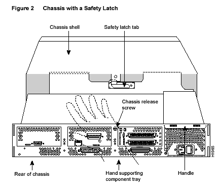
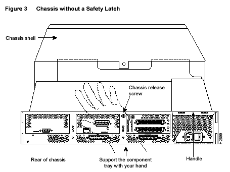
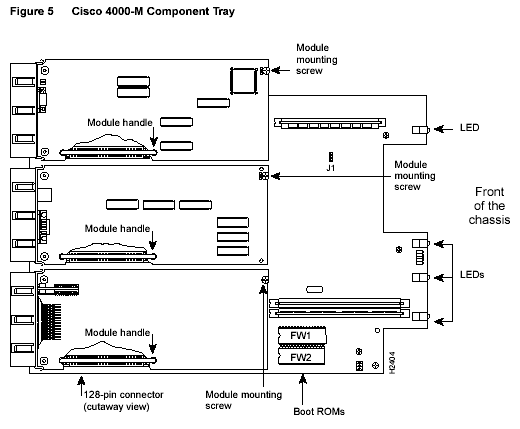
Cisco 4000 The Cisco 4000 router contains the following memory systems: Cisco 4000-M Cisco 4500 Cisco 4500-M Cisco 4700 Cisco 4700-M Warning : Before working on a chassis or working near power supplies, unplug the power cord on AC units; disconnect the power at the circuit breaker on DC units. The following Warning applies to routers with DC power supplies: Warning : Before performing any of the following procedures, ensure that power is removed from the DC circuit. To ensure that all power is OFF, locate the circuit breaker on the panel board that services the DC circuit, switch the circuit breaker to the OFF position, and tape the switch handle of the circuit breaker in the OFF position. Some Cisco 4000 series routers have a safety latch tab on the chassis (see Figure 2) and others do not (see Figure 3).
Step 5 Using a Number 2 Phillips screwdriver, loosen the nonremovable chassis release screw on the rear panel of the chassis. If your chassis has a safety latch (see Figure 2), slide the component tray out of the chassis shell just until the safety latch catches. Support the component tray with one hand, push down on the safety latch tab, and pull the component tray out the rest of the way. If your chassis does not have a safety latch (see Figure 3), support the component tray with one hand while you slide it out of the chassis shell. Step 7 Set the tray on your work surface.
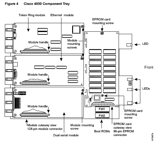
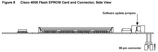
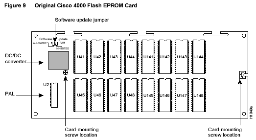
Follow these steps to remove the Flash EPROM card from a Cisco 4000 router in order to gain access to main memory, or to replace the original Flash EPROM card: Step 1 Using a Number 1 Phillips screwdriver, remove the two mounting screws from the top of the card and set them aside. See Figure 4 for the location of these screws. This figure shows the original Flash EPROM daughter card for the Cisco 4000; if your daughter card has been replaced, its appearance will differ. Caution: To prevent damage to the Flash EPROM card, handle it only by the sides. Step 2 Holding the Flash EPROM card by its edges, pull straight up to lift it out of its 96-pin connector. (See Figure 8.)
If you are also upgrading shared memory on the Cisco 4000 motherboard, continue with the section �Removing Network Processor Modules� later in this document. If you are upgrading only main memory on the Cisco 4000 motherboard, continue with the section �Memory Locations� later in this document. If you are installing a new Flash EPROM card, you may also need to install updated boot ROMs to provide support for the new card. If your boot ROMs are Cisco IOS Release 10.2(8) or earlier, continue with the section �Upgrading the ROM� later in this document. If your ROM supports a later version of the Cisco IOS, you do not need to replace the boot ROMs. Continue with the section �Installing the Flash EPROM Card (Cisco 4000 Router Only)� later in this document.
Follow the procedures in this section to install additional Flash EPROMs on the original Cisco 4000 Flash EPROM card, shown in Figure 4 and Figure 9. You must also replace the existing programmable array logic (PAL) device with a new PAL. Note You do not need to remove the Flash EPROM card for this upgrade procedure. Do not try to remove the existing Flash EPROMs; they are permanently installed. Caution: Correct placement of the Flash EPROMs and PAL is crucial. If improperly positioned, the new components could be damaged when you power ON the router.
Installing Flash-Memory EPROMs To install new Flash EPROMs in the eight open sockets (U141 to U148) on the Flash EPROM card (see Figure 9), align the notch in each EPROM with the notch in an EPROM socket. Insert the Flash EPROM into the sockets, being careful not to bend any pins. To straighten a bent pin, use needlenose pliers. All Flash EPROM sockets should be filled.
Replacing the Flash EPROM Card PAL Follow these steps to replace the PAL at location U2 in Figure 9: Step 1 Using an IC extraction tool or small flat-blade screwdriver, gently lift the existing PAL out of its socket, being careful not to damage the underlying printed circuit card. Step 2 Align the notch in the replacement PAL with the notch in the PAL socket. Insert the PAL into the socket, being careful not to bend any pins. To straighten a bent pin, use needlenose pliers.
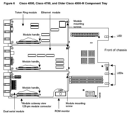
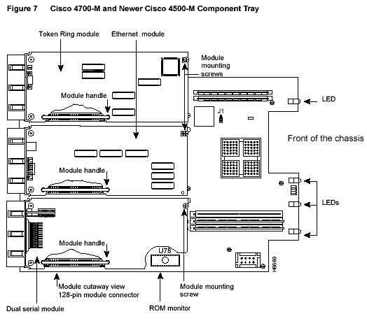
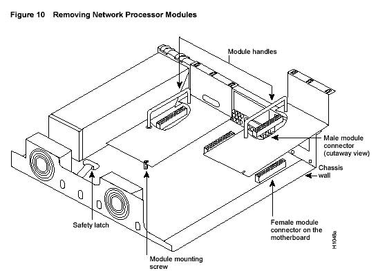
To enable or disable writing a new version of the Cisco IOS to Flash EPROM, set the jumper shown at the upper left of Figure 9. To allow software update (the factory-set default), place the jumper on the left two pins. To prevent software update, place the jumper on the right two pins. To replace the component tray in the chassis shell, continue with the section �Replacing the Component Tray� later in this document. To gain access to shared memory in all routers, you must remove the center network processor module from the component tray. In the Cisco 4000 router, you must also remove the module on the right (as viewed from the front of the router). To access the ROM monitor in Cisco 4500, Cisco 4500-M, Cisco 4700, and Cisco 4700-M routers, remove the module on the left. If you are upgrading only main memory or Flash memory in a Cisco 4000-M, Cisco 4500, Cisco 4500-M, Cisco 4700, or Cisco 4700-M router, or the ROM monitor in a Cisco 4000-M router, you do not need to remove network processor modules. Continue with the section �Memory Locations� later in this document. If you are upgrading main memory or Flash memory in a Cisco 4000 router, refer to the section �The Cisco 4000 Flash EPROM Card� earlier in this document. Caution: Some network processor modules are fastened to the rear of the chassis with two external screws. You must remove these screws before you can lift the module out of the chassis. Follow these steps to remove a module: Caution: Do not wiggle the module�s handle or exert any side-to-side pressure. The handle may work loose and damage the module.
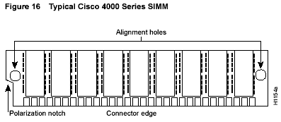
SIMM Orientation SIMMs are manufactured with a polarization notch to ensure proper orientation, and alignment holes that fit over guide posts to ensure proper positioning. Figure 16 shows the polarization notch and alignment holes on a typical SIMM. SIMMs vary in their physical dimensions and in the number, size, and location of components on the surface of the card, depending on the router they are installed in, the type of memory, and the SIMM manufacturer.
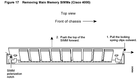
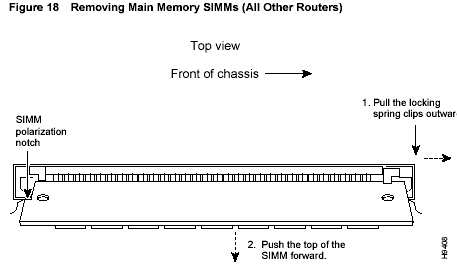
Caution: To avoid damaging ESD-sensitive components, observe all ESD preCaution:s when handling SIMMs. To avoid damaging the motherboard or the SIMM, avoid excessive force when you remove or replace SIMMs. Upgrading Main Memory A main-memory upgrade entails removing the existing main-memory SIMMs and replacing them with the upgraded SIMMs. If you are upgrading a Cisco 4000 router, you must first remove the Flash EPROM card. See the section �Removing the Flash EPROM Card� earlier in this document. Removing Main-Memory SIMMs Follow these steps to remove main-memory SIMMs: Caution: Handle SIMMs by the card edges only. SIMMs are ESD-sensitive components and can be damaged by mishandling. Step 2 Remove one SIMM at a time, beginning with the SIMM closest to the edge of the motherboard in the Cisco 4000, and the SIMM farthest from the edge of the motherboard in all other routers.
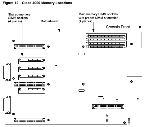
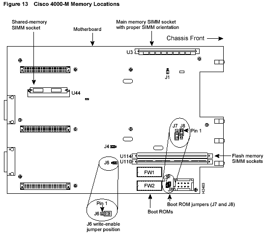
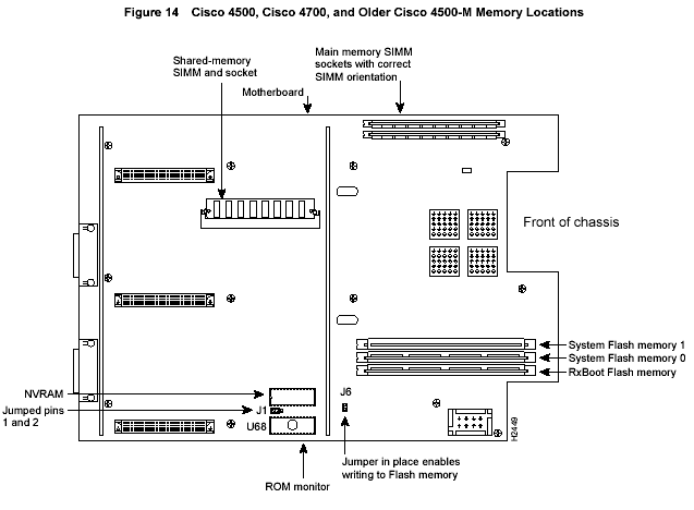
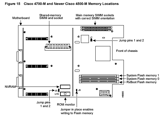
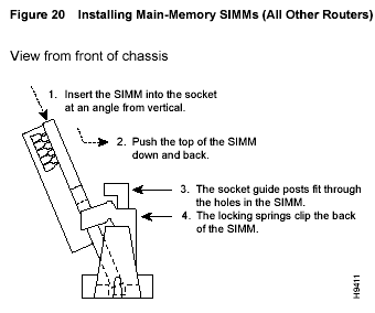
Installing Main-Memory SIMMs Follow these steps to install main-memory SIMMs: Step 1 Find the main-memory SIMM sockets on the router�s motherboard, as shown in Figure 12, Figure 13, Figure 14, or Figure 15. All sockets should be empty. If they are not, follow the steps in the previous section, �Removing Main-Memory SIMMs.� Caution: Handle SIMMs by the card edges only. SIMMs are ESD-sensitive components and can be damaged by mishandling. Step 2 Hold the SIMM with the connector edge at the bottom and the polarization notch toward the rear of the router. Step 3 Beginning with the socket farthest from the edge of the motherboard in the Cisco 4000, and the socket nearest the edge of the motherboard in all other routers, insert the SIMM at an angle, tilted toward the right side in the Cisco 4000, as viewed from the front of the router (see Figure 19), and toward the left side in all other routers (see Figure 20). Rock it into a vertical position, using the minimum amount of force required. When the SIMM is properly seated, the socket guide posts fit through the alignment holes, and the spring clips click into place. Step 4 Ensure that the SIMM is straight and that the alignment holes line up with the plastic guides on the socket. It is normal to feel some resistance, but do not use excessive force on the SIMM, and do not touch the surface components. Step 5 Repeat Step 2 through Step 4 for each main-memory SIMM. If you are finished upgrading memory, continue with the section �Installing the Flash EPROM Card (Cisco 4000 Router Only)� later in this document for a Cisco 4000 router, or the section �Replacing the Component Tray� for any other model.
A shared-memory upgrade entails removing the existing shared-memory SIMMs and replacing them with the upgraded SIMMs. You must first remove the network processor modules from the component tray. See the section �Removing Network Processor Modules� earlier in this document. Removing Shared-Memory SIMMs Follow these steps to remove shared-memory SIMMs: Step 1 Find the shared-memory SIMM sockets on the motherboard, as shown at the left of Figure 12, Figure 13, Figure 14, or Figure 15. These sockets hold the SIMMs horizontally. Caution: Handle SIMMs by the card edges only. SIMMs are ESD-sensitive components and can be damaged by mishandling. Step 2 The SIMMs are held in place at each end by spring clips. To remove a SIMM, pull the clips outward. Holding the SIMM by the edges with your thumb and index finger, angle it upward, and pull it out. Step 3 Place the removed SIMM in an antistatic bag to protect it from ESD damage. Step 4 Repeat Step 2 and Step 3 for any remaining shared-memory SIMMs.
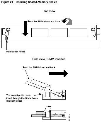
Follow these steps to install shared-memory SIMMs: Step 1 Find the shared-memory SIMM sockets on the motherboard, as shown in Figure 12, Figure 13, Figure 14, or Figure 15. All sockets should be empty. If they are not, follow the steps in the previous section, �Removing Shared-Memory SIMMs.� Caution: Handle SIMMs by the card edges only. SIMMs are ESD-sensitive components and can be damaged by mishandling. Step 2 Hold the SIMM with the polarization notch toward the rear of the router and the connector edge toward the left side of the router (as viewed from the front). Step 3 To insert a SIMM, angle it into position (see Figure 21), then carefully push down and back on the edges, holding each edge so that it snaps securely into place. The two spring clips should fit over the edge of the SIMM and hold it horizontally. Step 4 Ensure that the SIMM is straight and that the alignment holes line up with the plastic guides on the socket. It is normal to feel some resistance, but do not use excessive force on the SIMM, and do not touch the surface components. Step 5 Repeat Step 2 through Step 4 for any remaining shared-memory SIMMs.
If you are finished upgrading memory, continue with the section �Replacing Network Processor Modules� later in this document. Upgrading Flash Memory Flash memory in the Cisco 4000 router resides on a separate daughter card. To add memory to the original daughter card, see the section �Adding Memory to the Flash EPROM Card� earlier in this document. To replace the card, see the sections �Removing the Flash EPROM Card� and �Installing the Flash EPROM Card (Cisco 4000 Router Only).� When you upgrade the Flash EPROM card, you also install new boot ROMs (which are included in the upgrade kit) and change the boot ROM jumpers (J5 and J6). To upgrade system Flash memory in other routers, add a second Flash SIMM. For the Cisco 4500-M, Cisco 4700, and Cisco 4700-M routers, you can also replace 4-MB Flash-memory SIMMs with 8-MB SIMMs. In all routers, when both system Flash-memory sockets are filled, equal memory sizes are required.
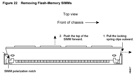
To remove a Flash-memory SIMM, follow these steps: Step 1 Find the system Flash-memory sockets on the motherboard, as shown at the lower right of Figure 13, Figure 14 or Figure 15. These sockets hold the SIMMs vertically. Caution: Handle SIMMs by the edges only. SIMMs are ESD-sensitive components and can be damaged by mishandling. Step 2 Remove any SIMMs that you want to replace, beginning with system Flash memory socket 1, as shown in Figure 13, Figure 14, or Figure 15. Pull the spring clips on both sides outward and tilt the SIMM free of the clips, toward the right side of the router, as viewed from the front. (See Figure 22.) Step 3 Hold the SIMM by the edges with your thumb and index finger and lift it out of the socket. Place the removed SIMM in an antistatic bag to protect it from ESD damage. Step 4 If necessary, repeat Step 2 and Step 3 for the SIMM in system Flash memory socket 0.
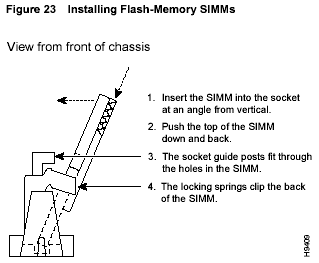
Installing Flash-Memory SIMMs To install a Flash-memory SIMM, follow these steps: Step 1 Find the system Flash-memory sockets on the motherboard, as shown in Figure 13, Figure 14, or Figure 15. Caution: Handle SIMMs by the edges only. SIMMs are ESD-sensitive components and can be damaged by mishandling. Step 2 Hold the SIMM with the connector edge at the bottom and the polarization notch toward the rear of the router. (See Figure 23.) Step 4 Ensure that the SIMM is straight and that the alignment holes line up with the plastic guides on the socket. It is normal to feel some resistance, but do not use excessive force on the SIMM, and do not touch the surface components. Step 5 If socket 0 is already filled, or to install a second Flash-memory SIMM, repeat Step 2 through Step 4 for system Flash memory socket 1. If you are finished upgrading memory, continue with the section �Replacing the Component Tray� later in this document.
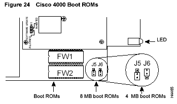
Upgrading the ROM To upgrade the ROM monitor on a Cisco 4500, Cisco 4500-M, Cisco 4700, or Cisco 4700-M router, you must first remove the network processor modules. See the section �Removing Network Processor Modules� earlier in this document. You can upgrade the boot ROMs on the Cisco 4000 and Cisco 4000-M without removing network processor modules. Caution: Correct placement of the ROM is crucial. If improperly positioned, the new ROM could be damaged when you power ON the router. Follow these steps to replace the ROM: Step 1 Locate the ROM or ROMs on the motherboard, as shown in Figure 12, Figure 13, Figure 14, or Figure 15. Step 2 Gently remove the old ROM with an IC extraction tool or a small flat-blade screwdriver, and set it aside. Step 3 Align the notch in the new ROM with the notch in the socket, ignoring the orientation of the label. Insert the ROM in its socket, being careful not to bend any pins. To straighten a bent pin, use needlenose pliers. Caution: The notch on the ROM must match the notch on the socket. Installing the ROM backward will damage it. Step 4 For Cisco 4000 routers only, set jumpers J5 and J6 to designate the capacity of the Boot ROMs. For boot ROMs version Cisco IOS Release10.2(8) and higher short pins 2 and 3 on both jumper locations, J5 and J6 as shown in the 8 MB boot ROMs position. To short pins 2 and 3 on J5 and J6, install the jumper block over the two pins located away from the Flash EPROM card, as shown in the 8 MB boot ROMs position on Figure 24. For 4 MB boot ROMs, which are prior to version 10.2(8), install the jumper on the upper two pins at J6 and the lower two pins at J5.
Step 1 Line up the card with the 96-pin socket and screw holes. (See Figure 8.) Caution: Do not overtorque the screw. The card or the underlying motherboard could be damaged. The maximum screw torque is 7 inch-lb. Step 4 After you upgrade the Flash EPROM card, install the new boot ROMs included in the kit (part number MEM-4000-8F=) and set jumpers J5 and J6 using Step 1 through Step 4 in the previous procedure. Step 5 Once the Flash EPROM card has been replaced, the boot ROMs have been replaced, and the boot ROM capacity jumpers have been set, replace the component tray in the chassis. If you removed network processor modules to gain access to shared memory or the ROM monitor, follow these steps to replace them: Step 1 Pick up the module by its handle, align it with the guides on the component tray rear panel, and hold it gently against the chassis wall. (See Figure 10.) Step 2 Push the module carefully into place, inserting its male connector into the female connector on the motherboard without bending the pins. Step 3 Using a Number 1 Phillips screwdriver, replace the internal module mounting screw on the end of the module card. (See Figure 10.) Step 4 Replace the external rear mounting screws, if any, in the rear panel. Caution: Do not overtorque the screws, because this can damage the module or the underlying motherboard. The maximum screw torque is 7 inch-lb. Replacing the Component Tray Follow these steps to replace the component tray in the chassis shell: Step 1 Insert the component tray into the shell, pushing on the back of the tray while pressing on the chassis release screw (shown in Figure 2 or Figure 3) with the thumb of your other hand.
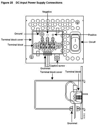
Follow these steps to make final connections to the router: Step 1 Replace all network connections. Step 2 If you have an AC-powered router, plug the power cord into a 3-terminal, single-phase power source that provides power within the acceptable range (100 to 240 VAC, 50 to 60 Hz, 3.0 to 1.5 A).If you have a DC-powered router, rewire the DC-input power supply (40 to 72 VDC) to the terminal block. The proper wiring sequence is ground to ground, positive to positive, and negative to negative. (See Figure 25.) After connecting the DC power cables, use a Warning : After wiring the DC power supply, remove the tape from the circuit breaker switch handle and reinstate power by moving the handle of the circuit breaker to the ON position. Step 3 Turn ON the power switch. The power LED on the front should go ON. Step 4 Check the OK LED on the right side of the front panel to verify that it goes ON after a few seconds delay when booting.
If you installed a new ROM incorrectly, the router may fail to boot. Following the procedures in this document, gently remove the old ROM with an IC extraction tool or a small flat-blade screwdriver, and set it aside. Use needlenose pliers to straighten any bent pins on the ROM. Then reinstall it carefully, reassemble the router, and try booting again. If you have questions or need help, refer to the sections �Cisco Documentation� and �Cisco Connection Online� later in this document.
Cisco documentation and additional literature are available in a CD-ROM package, which ships with your product. The Documentation CD-ROM, a member of the Cisco Connection Family, is updated monthly. Therefore, it might be more up to date than printed documentation. To order additional copies of the Documentation CD-ROM, contact your local sales representative or call customer service. The CD-ROM package is available as a single package or as an annual subscription. You can also access Cisco documentation on the World Wide Web at http://www.cisco.com, http://www-china.cisco.com, or http://www-europe.cisco.com.
CCO serves a wide variety of users through two interfaces that are updated and enhanced simultaneously: a character-based version and a multimedia version that resides on the World Wide Web (WWW). The character-based CCO supports Zmodem, Kermit, Xmodem, FTP, and Internet e-mail, and it is excellent for quick access to information over lower bandwidths. The WWW version of CCO provides richly formatted documents with photographs, figures, graphics, and video, as well as hyperlinks to related information.
For a copy of CCO�s Frequently Asked Questions (FAQ), contact [email protected]. For additional information, contact [email protected]. Note If you are a network administrator and need personal technical assistance with a Cisco product that is under warranty or covered by a maintenance contract, contact Cisco�s Technical Assistance Center (TAC) at 800 553-2447, 408 526-7209, or [email protected]. To obtain general information about Cisco Systems, Cisco products, or upgrades, contact 800 553-6387, 408 526-7208, or [email protected].
This document is to be used in conjunction with your router installation guide and the Cisco 4000 Series Regulatory Compliance and Safety document.
|
� Copyright 2008, All right reserved, CiscoMemoryUpgrade